

A conference venue without dedicated internet access, a match taking place far from the studio, several events sharing one control room: in each case, the available connection and the way the crew is organised determine how much production can happen remotely.
Bonding uses several connections to carry a live stream. REMI, or remote production, distributes production tasks between the venue and a remote control room. Together, they can reduce travel and the number of people needed on site. Planning starts with the streams to be carried, the acceptable delay and what should happen when a link degrades.
Cellular bonding and REMI: complementary functions
Cellular bonding combines multiple links, including 4G/5G connections, to carry a single stream. Depending on the equipment, it can also use an internet connection reached over Ethernet or Wi-Fi, and a satellite link. Here, Ethernet and Wi-Fi refer to the connection to the venue’s network; usable throughput depends on the internet service behind it.
REMI (Remote Integration Model), also known as remote production or at-home production, moves part of the production work away from the venue. Cameras and microphones stay on site, while directing, graphics, audio mixing or distribution can move elsewhere. Video processing may stay at the venue or move to the control room, depending on the architecture.
The potential savings include travel and on-site staffing. Production roles still need to be covered, and crew size depends on the cameras, how they are operated and the programme. A shared control room can support several events, subject to scheduling and capacity.
The two techniques work independently: a REMI production can use a single fibre connection, while bonding can support a programme produced entirely on site.
Bonding, load balancing and failover
A multi-WAN device has access to several network connections. It may offer one or more of the functions below; the number of ports or SIM slots does not show which of these functions are available.
| Function | Principle | What to check for a live broadcast |
|---|---|---|
| Bonding | Distribute packets from one stream across several links, then bring them together at the receiving end | Usable throughput and stream continuity after a link fails |
| Load balancing | Distribute sessions across connections; in conventional per-session operation, each stream stays on one link | A single stream does not receive the combined bandwidth; a failure may require it to reconnect |
| Failover | Switch to a backup connection when the primary connection fails | Detection time, any change of IP address and the interruption actually observed |
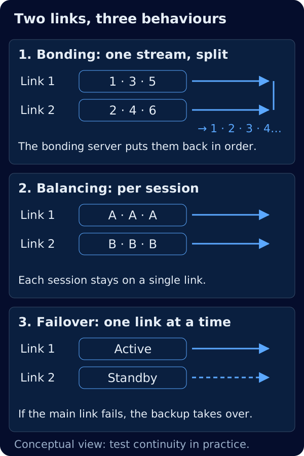
In a tunnel-based bonding system, a remote server, known as the bonding server, brings the packets together and provides the internet exit point. Its location and capacity are part of the path that must be assessed. Usable throughput does not necessarily equal the sum of separate speed tests: transport overhead and differences in link quality also matter.
Duplication takes another approach: multiple links carry copies of the same packets. It uses more data to reduce the impact of packet loss. Speedify documents modes that favour speed, redundancy or adaptation to real-time traffic. Which modes a device offers depends on how Speedify is integrated. The principles and server options are explained on the Speedify page and in its channel bonding documentation.
Two SIM slots guarantee neither two simultaneously active modems nor bonding. Subscriptions using the same network, including through a mobile virtual network operator (MVNO), may suffer a shared outage or congestion. Different operators improve diversity without guaranteeing completely independent infrastructure. Also check that a backup Wi-Fi connection does not depend on the same internet service as the primary link.
Where are the switcher and the operator?
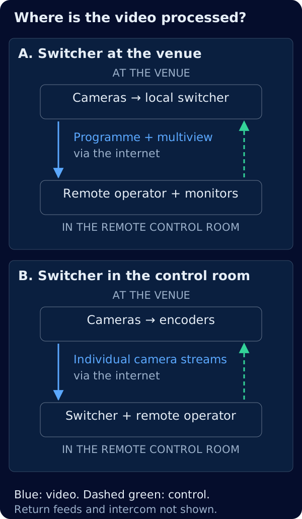
They do not have to be in the same place. A switcher at the venue can be operated remotely when its control features and the network support this. The operator also needs the monitoring pictures and status information required to direct the programme.
Switcher at the venue, directed locally or remotely
Sources feed a local switcher, which produces a programme stream. The director may work locally or remotely. With a remote director, the programme and a multiview (a mosaic showing several sources on one screen) can travel to the control room while commands travel back to the venue. This reduces the number of contribution streams, but monitoring quality and delay become critical.
Switcher in the control room, cameras sent individually
Each camera is encoded and sent separately. The control room switches the programme from those contributions. Upload requirements increase with the number of streams, and their timing and audio/video synchronisation must be checked. An SRT buffer on each stream does not, on its own, guarantee synchronisation between cameras: the encoders’ and receivers’ synchronisation features need to be validated together.
A hybrid setup with a backup programme
A local switcher can prepare a simpler programme if carrying the individual contributions becomes difficult. This requires a receiving path and a tested switchover procedure. It cannot keep the broadcast online if all connections disappear; a local recording can preserve the content in that situation.
Each architecture has four groups of traffic to account for:
| Traffic | Main direction | Requirement to assess |
|---|---|---|
| Contribution | Venue to control room | Sustained video and audio throughput, loss, synchronisation |
| Programme return | Control room to venue | Download capacity and delay suited to screens and presenters |
| Intercom and signalling | Bidirectional | Intelligible conversation, low delay, appropriate network priority |
| Control and monitoring | Commands to the venue, status and pictures to the operator | Secure access, responsiveness; count multiview bandwidth separately |
Three field setups
Single-camera live report over cellular bonding
On location, a camera feeds an encoder that sends SRT to the control room through a bonding router. The control room can monitor the connection so that the camera operator does not have to take sole responsibility for it.
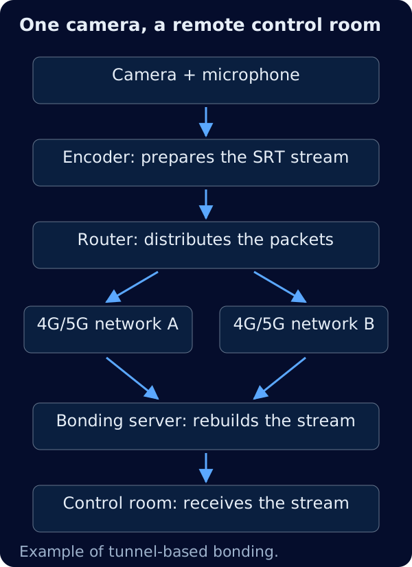
The Miri V410 and Miri X510, from Miri Technologies, illustrate the encoding and connectivity roles respectively. A configuration still needs to be checked against its video inputs, codecs, bitrates and supported functions. Local recording and battery runtime are part of the preparation.
Several cameras without dedicated internet access
PTZ cameras can connect to a network switch, using PoE where the camera models and the switch’s power budget support it. With NDI® sources, sending SRT requires a gateway compatible with the NDI variant in use, unless the camera has its own SRT output.
Whether to send individual sources or a local programme determines the internet requirement. The remote PTZ control use case describes an approach using BirdDog Connect; compatibility with the chosen setup still needs checking. Cellular coverage, audience-related congestion and installation requirements for any satellite terminal need to be assessed at the venue.
A wired venue with a recurring programme
Fibre can carry the regular production, with cellular available as backup. Conventional failover may be sufficient if the observed interruption is acceptable. Where session continuity is required, a tunnel-based bonding or redundancy solution can be considered and tested. That decision applies to the programme sent to a streaming platform as well as to return feeds and intercom.
Even with a remote control room, having someone at the venue who can attend to cables, power and equipment remains useful.
Sizing bandwidth and backup capacity
The following example is hypothetical. It illustrates a calculation method, not measured performance or a universal recommendation for picture quality.
Assume four 1080p50/H.264 contributions, each configured at a total payload rate of 6 Mbit/s including audio, for 90 minutes. Picture quality needs to be assessed with the actual content. A more efficient codec may reduce the requirement, but the benefit depends on the encoder, settings and receiver compatibility.
1. Count traffic in both directions
Four streams at 6 Mbit/s require 24 Mbit/s of upload payload. A hypothetical programme return at 4 Mbit/s needs to be budgeted on the download side. Add intercom, signalling, any monitoring feed and protocol control traffic separately. A return feed does not add its full video bitrate to the upload requirement, but network communication is not strictly one-way.
2. Allow headroom, then measure usable throughput
In this example, a planning margin of 25% brings the contribution budget to 30 Mbit/s. It does not represent continuous consumption. Other traffic and tunnel overhead still need to be covered, taking account of what the throughput test actually measures.
SRT provides a configurable retransmission budget, notably through SRTO_OHEADBW. That setting does not reserve capacity with the internet provider. The Haivision SRT documentation explains how it works. Final sizing must reflect the loss and variability observed across the actual transmission chain.
3. Check capacity after a failure
Assume three connections provide upload rates of 25, 12 and 15 Mbit/s. Their arithmetic sum is 52 Mbit/s; that is not a measurement of usable bonded throughput.
After losing the 25 Mbit/s link, the other two add up to 27 Mbit/s. The planned 30 Mbit/s contribution budget is no longer covered, even before other traffic is counted. The streams may still get through under favourable conditions, but the chosen headroom is gone. If remaining usable throughput falls below the 24 Mbit/s payload rate, the configured bitrate cannot be sustained.
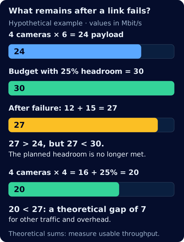
Possible responses include reducing each camera’s bitrate, using bitrate adaptation supported by the equipment, or switching to the local backup programme. At 4 Mbit/s per camera, the payload drops to 16 Mbit/s and the budget reaches 20 Mbit/s with headroom, 7 Mbit/s below the theoretical 27 Mbit/s remaining. That gap still has to cover other upstream traffic and overhead, subject to the usable throughput actually measured. Picture quality and behaviour during a failure also need to be validated at that setting.
4. Calculate data volume
At 24 Mbit/s, payload amounts to 3 MB/s, or 16.2 GB over 90 minutes. A single programme at 8 Mbit/s amounts to 5.4 GB over the same period, using decimal units.
These figures exclude network overhead, retransmissions, duplication and other traffic. Usage on each subscription depends on the traffic actually carried by that link; how a software licence counts data depends on its terms. Allow for rehearsals and testing when checking quotas.
Test end-to-end latency
Encoding, transport, receive buffers, decoding and display all contribute to the latency an operator experiences. A larger buffer may absorb more variation, but it also delays the pictures. Test the feed used to frame a PTZ shot or switch cameras, along with the intercom conversation. A stable picture can still arrive too late for comfortable operation.
Checks before going live
- Test connections at the venue at a representative time, then monitor changes as the audience arrives.
- Identify the networks in use and shared failure points: internet service, power, router or bonding server.
- Check antennas, their placement and the operating conditions of any satellite connection.
- Select the bonding server for the route, capacity and IP address requirements. Self-hosting gives control over that server, not every network on the path.
- Disconnect links in turn during transmission and observe the programme, return feed, intercom and controls.
- Run an extended test with simultaneous streams, backup procedures and the headsets and screens intended for the event.
- Validate SRT encryption at both ends and protect management interfaces with authenticated remote access, without exposing them directly to the internet.
- Check local recording, available storage, power runtime and who will be on hand at the venue to deal with problems.
Start with the production and the venue
The starting point is the programme: required sources, operator locations, acceptable delay and the service expected during a failure. Bonding and REMI can then support the appropriate production setup. Validation depends on the actual streams and on tests under degraded conditions, not just a speed test.
For more on video transport, see the NDI, SRT, RTSP and RTMP guide. To find a sales contact, the Where to buy page lists dealers; contact HoriCast to discuss the requirements and project direction.